Introduction
EMC Corporation commissioned Demartek to perform a hands-on
evaluation of EMC’s new entry-level CLARiiON AX4 iSCSI storage system.
This evaluation included installing and deploying the AX4 in the
Demartek lab facilities and reviewing several features including system
installation configuration, provisioning storage to hosts, capacity
expansion, data migration within the system, and creation of snapshot
copies. All features evaluated by Demartek are included with the base
CLARiiON AX4 system.
This report shows the actual steps taken to install and use the AX4 storage system. Screen shots are included.
Evaluation Summary
We found that the AX4 is easy to configure and use. In our opinion,
it is an ideal choice for customers consolidating storage for the first
time. It provides a strong set of storage management features in an
entry-level system, offers a great growth path, and is competitively
priced.
Overview of the EMC CLARiiON AX4
The CLARiiON AX4 is EMC’s entry-level iSCSI storage system for new
installations or consolidated applications. Storage capacities start
with as little as 600 gigabytes (GB) and can scale up to 45 TB now and
up to 60 TB of raw capacity when 1 TB disk drives are supported later in
the first calendar quarter of 2008. This type of solution is suitable
for block-oriented applications such as Microsoft Exchange, Microsoft
SQL Server, and backup and recovery.
The CLARiiON AX4 is available in either single or dual controller
models. The combination of the CLARiiON AX4 architecture, based on Intel
Xeon processors, and the CLARiiON FLARE operating environment enable
the system to scale from as few as 4 drives up to as many as 60 drives
within the system (up to four optional Disk Array Enclosures). The
combination of Intel’s advanced multiprocessor capability and high
degree of data path protection, complement the strengths of FLARE. Such
scalability (in both power and capacity) in an entry-level system is
rare, and offers a solid growth path for end-users.
These enclosures can be populated with Serial-Attached-SCSI (SAS)
disk drives for performance-sensitive applications and SATA disk drives
that provide large capacity for applications such as backup-to-disk.
For those installations needing multiple tiers of storage, the disk
drive types can be mixed SATA and SAS, even on the same shelf, as they
were for this evaluation. SATA disk drives are available in capacities
of 750 GB, with 1 TB SATA drive support coming in Q1’08. SAS disk drives
are available in 146GB and 400 GB capacities.
The iSCSI version of the AX4 has a total of four iSCSI host data
interfaces, two per storage processor. There is also a version of the
AX4 with four Fibre-Channel host data interfaces. This report focuses on
the iSCSI version only. Aside from the host interfaces, these two
versions of the AX4 are nearly identical.
The CLARiiON AX4 base system comes with an impressive suite of
software features. Software capabilities that ship with the system
include: wizard-driven installation utilities, simple configuration and
management, path management and failover, online capacity expansion,
non-disruptive data migration, and local snapshot replication for backup
operations.
Installation of the EMC CLARiiON AX4
The installation of the AX4 can be organized into the following general steps.
- AX4 hardware installation and system initialization
- Host server installation of PowerPath software and iSCSI session configuration
Hardware Installation
EMC has designed the AX4 to be installed by customers. A
“placemat” showing all the hardware installation steps comes with the
unit. In this evaluation, Demartek required less than an hour to unpack
the boxes, load the unit into the racks, connect all the cables, turn on
power to the system and get ready to perform the initial configuration
of the system.
System Initialization
The basic steps to the system initialization are:
- Discover the array
- Set the management port network settings
- Set the iSCSI data port network settings
- Set the administrative username and password
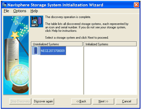
The Navisphere Storage System Initialization utility can be run
directly from the CDROM or installed on a host server. This utility
scans for, and automatically detects, the AX4 systems on the same subnet
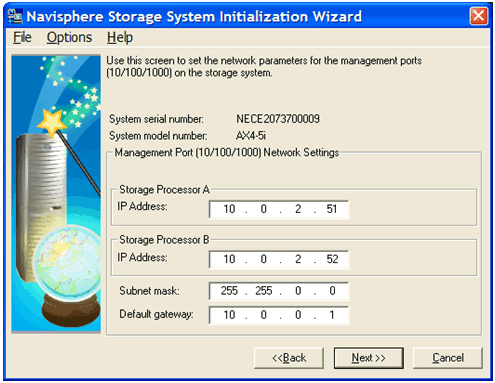
as the host server. After detection, the administrator can enter the
desired IP addresses for the management ports and the iSCSI data ports.
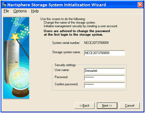
The administrator also sets the username and password for the
administrative access to the system. This process required approximately
10 minutes. We believe that any administrator generally familiar with
IP networking concepts will have no trouble configuring the AX4 iSCSI
storage system.
After setting the IP addresses for the AX4 management ports, the IP
addresses and other network configuration parameters are needed for the
four iSCSI data ports.
Following the network parameter settings, the only remaining
initialization task is to set the administrator username and password.
A final summary checklist is displayed, with the opportunity to go back and change any of the previous settings, if necessary.
After the AX4 has been installed and initialized, the host
servers that will access the iSCSI storage need to be prepared. The
servers in the Demartek lab have server-class NICs installed suitable
for iSCSI traffic and the Microsoft iSCSI software initiator already
installed.
The host server installation steps include the following:
- PowerPath Installation
- Configure Host Sessions
PowerPath Installation
The AX4 comes with EMC PowerPath at no additional charge, and is
required to provide the proper management as well as load balancing and
path failover for highly available connectivity to the AX4. In the
Microsoft Windows environment, PowerPath works with the Microsoft iSCSI
initiator. PowerPath must be installed on each host server that will use
the iSCSI storage of the AX4. For this evaluation, three servers in the
Demartek lab were used, running Windows Server 2003 R2 Enterprise x64
Edition.
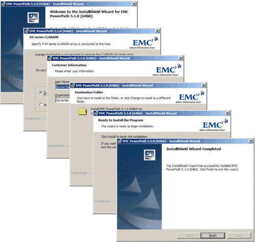
Installing PowerPath is a very straightforward process, simply
following the prompts. This process required less than five minutes per
host server. A reboot of the host server is required in order to
complete the installation. After PowerPath is installed, very little
user interaction with PowerPath is required for basic operation of the
AX4.
Host Session
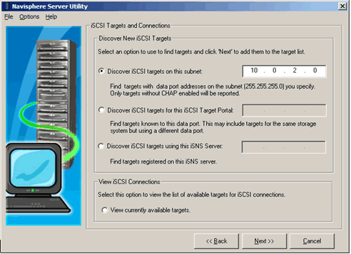
The Navisphere Server Utility steps through the process of
establishing a session between a host server and the AX4 system. Just a
few clicks are required to create and logon to an iSCSI session between
the host server and the AX4. This process took less than ten minutes per
host server.
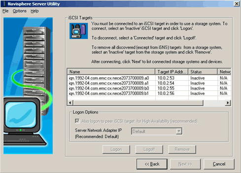
The iSCSI Target and Connections step will discover all iSCSI storage
visible to the host. At the time of this installation, only the AX4
iSCSI storage was visible to the three host servers.
The Navisphere Server Utility can logon and establish the iSCSI session
using all available host ports and connect to all available iSCSI target
ports. If the logon option is chosen, it will immediately logon to the
AX4 IQN (iSCSI Qualified Name) that is selected and its pair partner. In
this example, the IQN that ends with “a0” and “b0” are considered
partners and “a1” and “b1” are considered partners. The logon is also
established as a persistent iSCSI connection, so that whenever the host
server is rebooted, the iSCSI session is automatically reestablished at
system startup without user intervention.
The overall installation process was simple and straightforward.
We believe that any administrator familiar with basic IP networking
concepts would have no trouble installing an AX4 system.
Managing the CLARiiON AX4 Using Navisphere Express
EMC provides the Navisphere Express software to manage the AX4. The
Navisphere Express provides wizards to assist with many of the
functions, making them easy to perform. The basic functions include:
1. System administration settings
2. Host server information
3. Storage configuration
The first time Navisphere Express is launched, a few items that
need attention will be highlighted and these items can serve as a
checklist for some logical first steps for the administrator to insure
high availability and the best use of the AX4. The configuration of
these items is explained below.
System Administration Configuration
To begin our configuration, we changed the name of the system,
specified an email address to use for AX4 system notifications and set
the AX4 system time.
Host Server Configuration
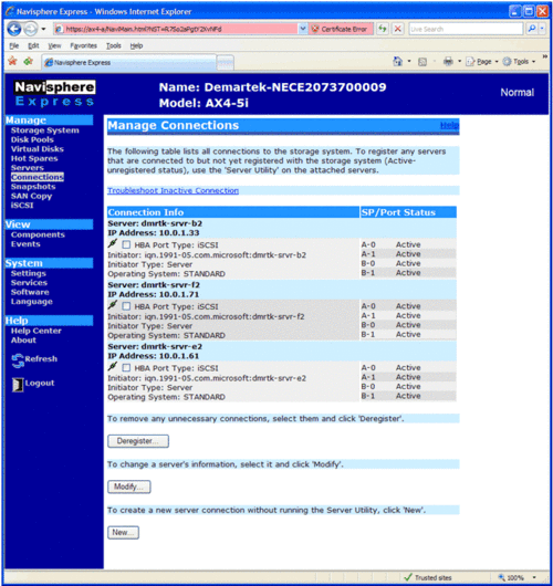
Clicking on the “Connections” menu item allows the administrator
to configure a host server connection. Four pieces of information are
required to complete this step:
- The IQN of the host server
- The operating system type
- The name of the host server
- The IP address of the host server
This series of steps is repeated for each desired server connection.
The connections are configured to use all available active iSCSI ports.
Here we see the results of configuring three host servers.
Up to 128 iSCSI initiators (64 high availability hosts) can be
configured. These can be physical hosts or hosts in a virtual server
environment such as VMware®.
Storage Configuration
For the storage configuration, the disk pools need to be created,
and hot spares need to be assigned. After creating disk pools, virtual
disks are created that can be assigned to host servers. If the host
servers have already been configured, then the virtual disk can be
assigned to specific host servers when they are created. If the host
servers have not been configured, the virtual disks can be assigned
later.
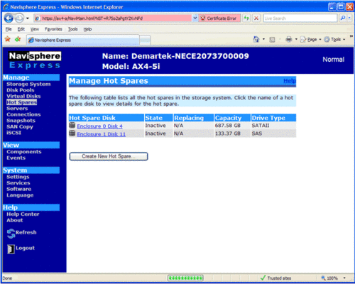
Because the evaluation unit included both SATA and SAS disk
drives, we configured one hot spare of each type before configuring the
disk pools. In this example we see that one SATA and one SAS disk drive
are listed as a “Hot Spare” disk.
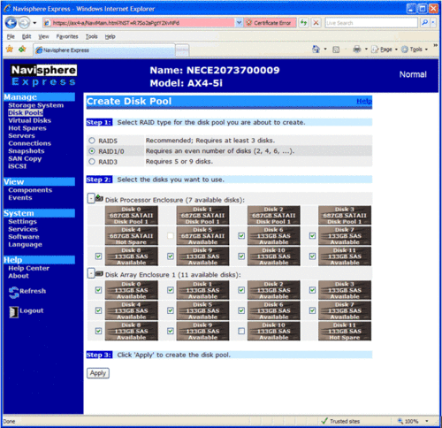
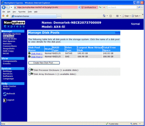
We configured two disk pools, one for each type of disk. This allows us to create a two-tier storage system.
The SAS disk pool spans enclosures. Disk pools can span enclosures and can have up to 16 disk drives per pool.
After creating these disk pools, we configured the remaining available disk drives as hot spares.
There is no limit to the number of disk pools that can be created. The
physical number of disks and the type of RAID grouping are the limiting
factors.
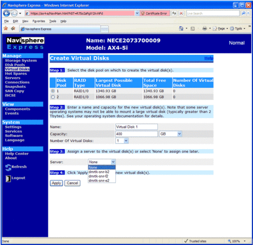
After creating disk pools, virtual disks are created and assigned
to specific hosts. The virtual disk creation process is
straightforward, requiring the following pieces of information:
- Disk pool from which to create the virtual disk
- Name, capacity and number of virtual disks to create
- Server to assign the virtual disk when completed.
Virtual disks can be created one-at-a-time or can be created in
groups to expedite the process. If more than one virtual disk of the
same size is needed, the size and the number of virtual disks can be
specified with no server initially assigned. The host servers can be
assigned to virtual disks later.
A total of 512 virtual disks can be created with a maximum of 128
virtual disks per disk pool. A single initiator could have up to 256
virtual disks assigned to it. A dual-connected host, such as in our
configuration, can have up to 512 virtual disks assigned to it.
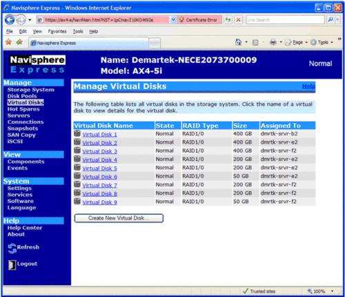
The creation of virtual disks is simple and easy, with all the
information needed available on one screen. The virtual disks must
complete their initialization before the host servers can access the
storage. This initialization time depends on the size of the virtual
disk and the type of disks (SATA or SAS) on which the virtual disks have
been created.
After the virtual disks have completed the AX4 system
initialization, they ready for use by the host servers. The host servers
follow normal procedures for creating partitions and formatting as with
any other disk storage
Online Capacity Expansion
Storage environments generally are not static and over time
individual storage volumes often need to be expanded. The AX4 provides a
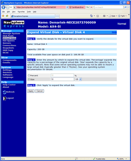
non-disruptive expansion function for virtual disks. If there is
unallocated capacity in a disk pool, a virtual disk can be expanded very
easily. The virtual disk expansion function allows for growth either by
a percentage or specific amount of storage. The administrator selects
the amount and presses “apply”. In this example, a 200 GB virtual disk
is expanded by 10 GB.
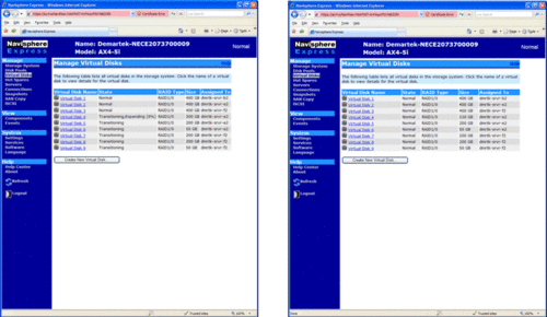
For a few minutes, while the virtual disk is expanding, its status is
displayed. When the expansion is complete, the host can then use
standard commands to expand the volume into the new space. In the
Windows environment, this step is accomplished by the “DISKPART”
command.
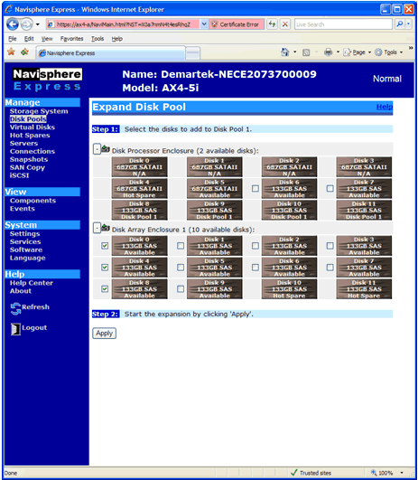
Disk pools can also be expanded easily and non-disruptively. The process
is similar to the virtual disk expansion process. In this example, we
began with a fresh RAID-5 disk pool that was originally configured with
four disk drives and expanded the pool to add three more drives, from
the second enclosure, to the pool.
"In-the-box" Data Migration
On some occasions, it will be advantageous to move a virtual disk
from one disk pool to another disk pool. This may be due to changing
performance requirements or to better utilize capacity. This process is
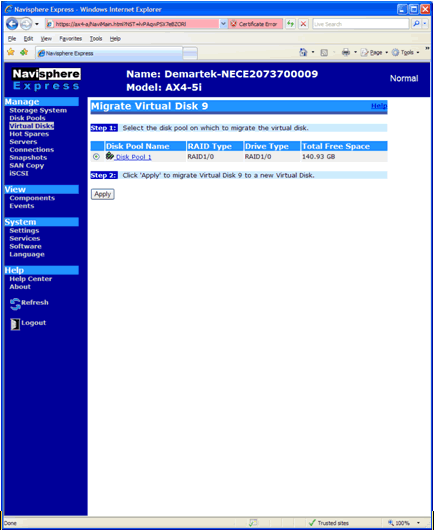
also easy to perform. In this example, we migrated virtual disk 9, from
disk pool 2 to disk pool 1. This process for migrating the data from SAS
drives to SATA drives was accomplished from the AX4 platform, without
any intervention required from the host server, and while the volume was
mounted by the host server. This “in-the-box” data migration feature is
extremely valuable for end-users deploying a mix of SAS and SATA drives
within the same system.
Snapshot Local Replication
There are many occasions where it is advantageous to have a
“point-in-time” copy of a virtual disk, known as a “snapshot” on the
AX4. Snapshots can be used for creating backup copies of data, test
copies of data or any other similar purpose. A snapshot copy can be
allocated to a secondary server without damaging the source data. The
second server has access to data and can read or write to the snapshot
copy. Up to 16 snapshots can be created per AX4, with one snapshot per
virtual disk.
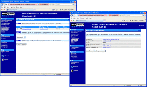
In this example, we use a 50 GB virtual disk allocated to one
server. Using the snapshot feature, we make a copy of this virtual disk
and allocate it to a second server. The process is simple and
straightforward.
On the hosts, the Navisphere Server Utility is then used to prepare the
snapshot on the first server and to allow access to it from the second
server.
Summary and Conclusion
As initially stated in the Evaluation Summary, we would like to confirm that the EMC AX4:
• Is an easy-to-use storage platform
• Is ideal for customers consolidating storage for the first time
• Is competitively priced, especially considering the software features included with the base system
• System scalability and Optional/Advanced software capabilities offers great growth path for end-users.
The AX4 is an easy to configure and easy to use iSCSI storage
solution. It provides flexibility for mixing disk drive types in the
same system to facilitate storage tiering; as well as easy migration of
virtual disks (host volumes) from one type of disk to another and easy
expansion of disk pools and virtual disks. Replication using the
AX4-based snapshot feature is simple and easy to perform.
With the included PowerPath software, multi-path configurations are straightforward.
Customers who are looking for an entry-level storage consolidation solution should strongly consider the CLARiiON AX4.
Appendix – Technical Specifications
This report was prepared by Demartek at the Demartek lab facilities
in Arvada, Colorado. The AX4 storage system was installed at the
Demartek lab and connected to three Demartek servers using an existing
Gigabit Ethernet infrastructure.
AX4 Technical Specifications
- 1 GB memory per SP, write caching only available on dual SP models.
- 4Gb/sec FC front end or 1 Gb/sec iSCSI front end
- 2U in height.
- 2 550W hot swappable power supply/blower modules.
The AX4 installed at the Demartek lab included:
- Dual-SP
- iSCSI model with four iSCSI host ports
- Two disk enclosures
- 24 disk drives (6 x 750 GB SATA, 18 x 146 GB SAS)
Action Item:
Footnotes: Report prepared under contract with EMC Corporation
Reprinted with permission © 2008
Demartek
See the full
June 2008 article at
Demartek
EMC and CLARiiON are registered trademarks of EMC Corporation.
VMware is a registered trademark of VMware, Inc.
All other trademarks are the property of their respective owners.
 2) Once you have selected create group, it will pop up raid group
creation wizard. Here you have to select so many option depending on
your requirement. First select RAID Group ID. This is unique id. Then
select how many disk. what it means? Let discuss for example you want to
create RAID 5(3+1) then you should select 4 disk. Means there will be 4
spindle
 Rest, you can select default. but suppose you want to create raid group on particular disk because in same CX Frame you can have different type of disk then you can select manual then select particular disk. under disk selection tab.
 Once you have selected the all the value you can click apply. It will create RAID Group with given configuration. It will pop up
message that RAID Group Created Successfully.If you want to create more
group you can create using wizard otherwise click cancel.
 Once you have created Raid Group you can bind the lun.
What is meaning of binding? Lets focus what happen when you created
RAID Group. Raid Group is something like storage pool. It will create
usable storage space according to number of disk you have selected and
raid group type. For example we have created Raid Group 4 and it size is
1600 GB. But you want to allocate 5 LUN each LUN size would be 100 GB or any combination of size until you you exhaust the space of the raid group. So it is call binding the LUN. Means, you have taken out some space for each LUN and allocated to Host. Each LUN
will have own properties but will belong to Raid Group 4. So in short
when you select number of disk while creating a particular group. CLARiiON Operating System will not allow you to use same disk of some other raid protection level.
 Once you have created all the LUN you can cancel that window and expand the particular raid group you can see that LUN will be listed.

